Brake Bracket Brainstorming
When we were given the Brake bracket plans i decided to use inventor. My first step would be to sketch it and then do extrusions.
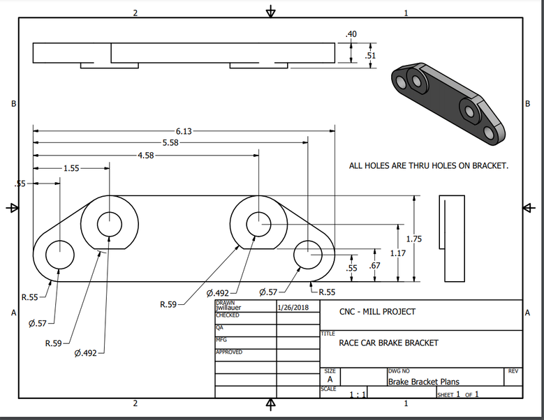
These are the plans that were given to us that I must follow.
Order of Creation (Recipe)
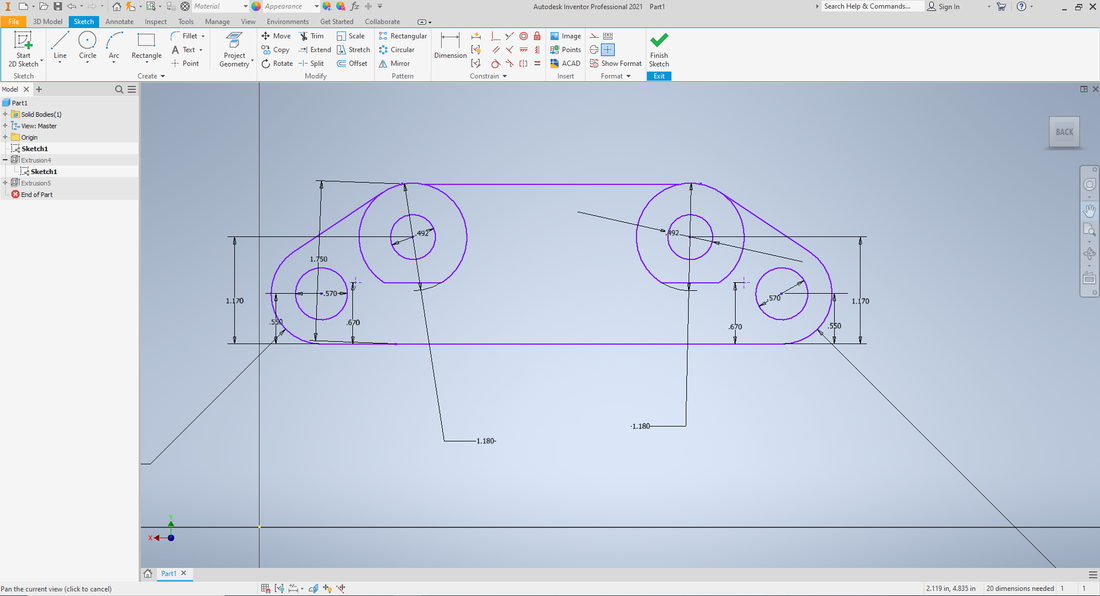
Here I have drawn the sketch of the brake pad. I started with a rectangle and "cut-out" from there. I have also made sure that the dimensions match the plans.
|
|
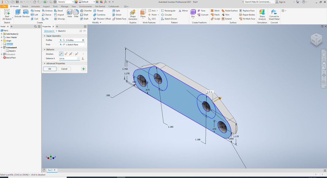
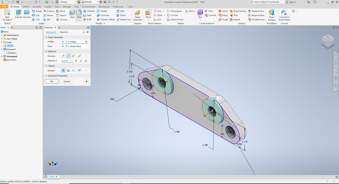
Here I extruded once, to get the first width of the brake bracket. Then I extruded a second time to get the raised circles.
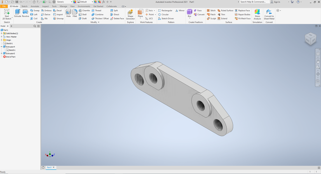
This is my finished brake bracket design in inventor. I have followed all instructions and dimensions on the sheet given to us.

|
We used this software, Fusion 360, to direct the paths of the mill for the print. We didn't get to using this ourselves but Ms. Proctor demonstrated it.
|
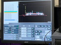
Here the G-Code is put into the CNC mill computer software and is running. the code tell the machine exactly where to move and drill in the material.
|
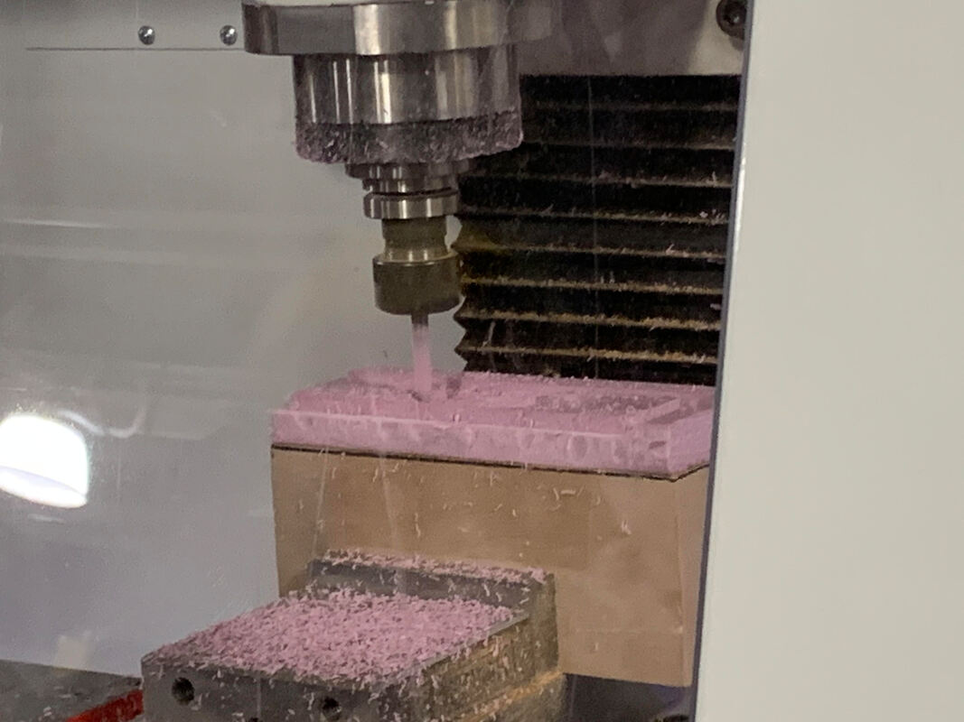
This is the CNC mill following the code and drilling out the brake bracket from foam material.
|
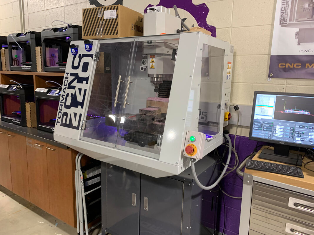
The CNC is also drilling here, you can also see the computer that is directing the motions of the drill.
|
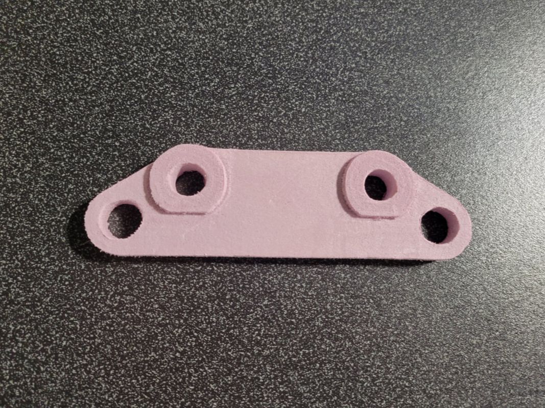
This is the finished brake bracket that Ms. Proctor made during her demonstration of Fusion 360 and the CNC mill.
What I learned
I learned very much over the course of this project. I refreshed my skills following blueprints and making in Inventor. In inventor I learned 2 new tools, tangent (which directs a line to another point) and a way to extrude two things at once using a plus icon. I also learned how to set up a design in Fusion 360 for the CNC mill. Fusion 360 directs the mill and shows the paths it must follow to create the object. We then learned how to setup the print in the mill using G-code from Fusion 360.
